Electronics
CPU
The Microprocessor chosen for this robot is the Motorola 6811 microcontroller. There are many variations of this microcontroller and some, especially models with large internal EEPROM are very difficult to obtain. There are a plethora of 6811 based microcontroller available commercially. After some searching, I decided on The Handy Board which was developed by Fred Martin at the MIT Media Laboratory. Here is a short technical specifications summary of The Handy Board:
- 52-pin Motorola 6811 microprocessor running at 2Mhz
- 32K of battery backup static RAM
- 4 PWM motor ports (output)
- 7 analog ports (input)
- 9 digital ports (input)
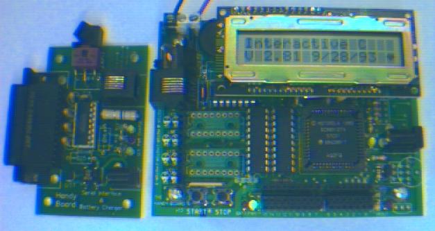
Handy board with serial interface
Motor controller
Although The Handy Board has four PWM motor ports, they are not suited for this robotics application. The motor's no load and full load (near stall) current are approximately 3 and 8A respectively. The motor driver chips and the PCB traces on The Handy Board cannot support such high current loads. Therefore some interface circuits are needed to take the control signals from The Handy Board to drive the motors.
It is important that the power source for the motors and CPU be isolated. If not, the noise generated by the motors will cause the CPU's logic circuits to function in an unpredictable manner. Plus, if something goes wrong with the motor controller you don't want it finding its way to the CPU.
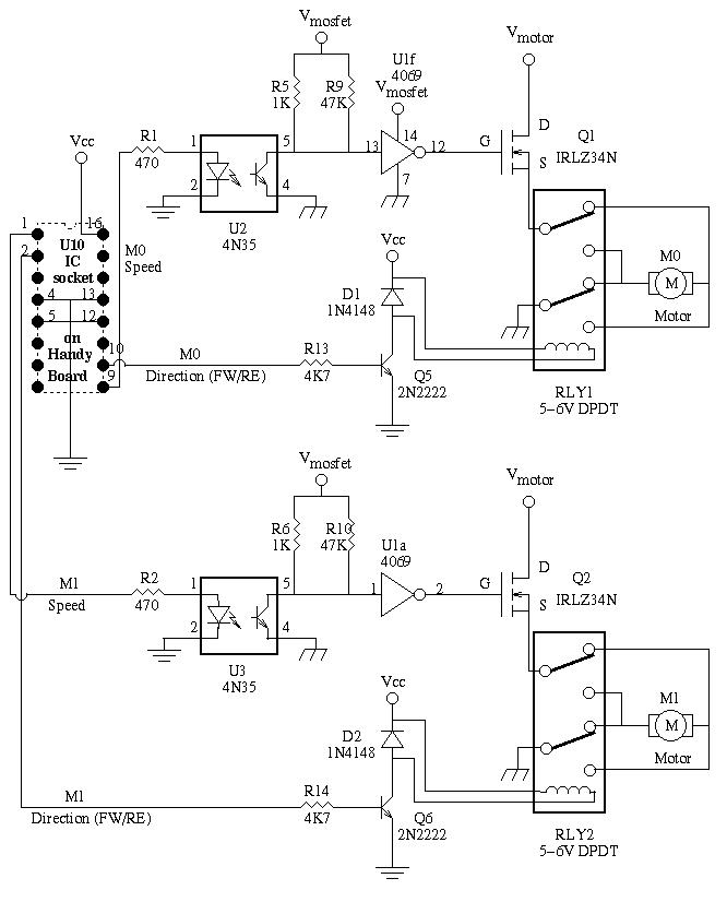
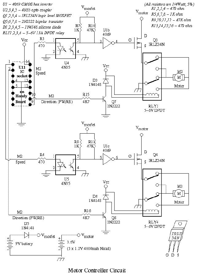
Pins 9 and 1 of U10 and U11 on the Handy Board are the Pulse Width Modulated (PWM) signal that controls the speed of the 4 motors (motor0-3). The PWM signals are routed through the 4N35 opto-couplers (U2,3,4,5) which have transistor outputs that inverts its input signal. Therefore, the output of the 4N35s must be inverted again with a 4069 CMOS Hex Inverter (U1) to ensure when there are no input signals the motors will be off.
Operating voltage of the motors (Vmotor) is 3.6V which is not sufficient to properly bias the IRLZ34N (Q1,2,3,4) logic level MOSFETs. To overcome this problem a 9V battery (Vmosfet) was used for U1 to drive the MOSFETs. Vmosfet's value of 9V is more the enought to ensure Q1,2,3, and 4 are biased properly.
The motors are connected to the MOSFETs through DPDT 5-6V relays (RLY1,2,3,4). They are wired to the relays in a manner such that when the 2N2222 transistors (Q5,6,7,8) connected to the coils of each relay are enabled by their respective signal from pins 10 or 2 of U10 or U11 on the Handy Board, the corresponding relay's coil(s) will energized. This reverses the polarity to the appropriate motor, thus, reversing its direction of rotation.
Vmosfet and Vmotor have common negative returns which are isolated from Vcc and its negative return as denoted by the different ground symbols used in the schematic diagram above.
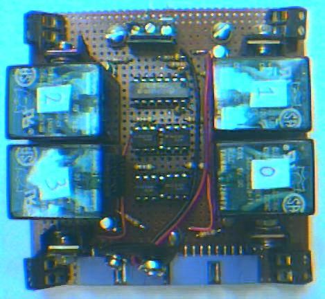
The completed motor controller
Obstacle detection sensor
The robot requires means of detecting an obstacle (or another robot) without making physical contact. This allows the robot to decide whether to avoid or to confront and investigate the obstacle depending on its programming. Ultrasonic transducers were chosen for this because they are more reliable and have a greater range than IR sensors (effectiveness of IR sensors varies with ambient light level).
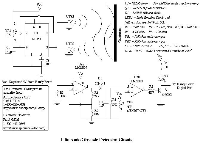
The IC U1 is a 555 timer in astable configuration to oscillate at 40KHz. Instead of using exact values for the two resistor that is placed between pin 6 and 7, a 10K ohm potentiometer (VR1) was used. This also allows for some fine tuning of the output frequency. The output (pin 3) is then attached to a 40KHz ultrasonic transmitter (UTR1).
The receiving circuit is a dual LM358N (U2) op-amp. A ultrasonic receiver (UTR2) is connected to pin 3, the non-inverting input of U2a which is a non-inverting amplifier with a gain of 220. The output of U2a is put through a low pass filter via D1, C3 and R4 to produce a some what stable DC voltage. This DC voltage is fed into the non-inverting input of U2b configured as a non-inverting comparator. Sensitivity of U2b is controlled by VR2 to set the threshold trigger value. The output of U2b is connected through R5 to the base of a bipolar 2N2222 transistor (Q1) acting as an inverter with a LED (LED1) to indicate if an obstacle has been detected. Finally, the collector of Q1 goes to the Handy Board's digital port (Handy Board uses inverted logic levels, 0V is a logic 1 and +5V is a logic 0).
The following is the procedure to calibrate the circuit without the use of an oscilloscope:
1) Adjust VR1 till the value between Vcc and pin 7 is approximately 1.2K ohm.
2) Place UTR1 and UTR2 parallel to each other (about 1.5 inches apart) with
a solid object about 6 inches in front of them (similar to figures UTR1 and
UTR2 in the above schematic).
3) If LED1 is off, turn VR2 CW till LED1 is on and then back off a bit till
it is just off. If LED1 is on, turn VR2 CCW till LED1 is just off.
4) Adjust VR1 (should only be about 1/4 turn CW or CCW) till LED1 turns on.
5) Repeat steps 3) and 4) as needed for optimal distance and sensitivities.
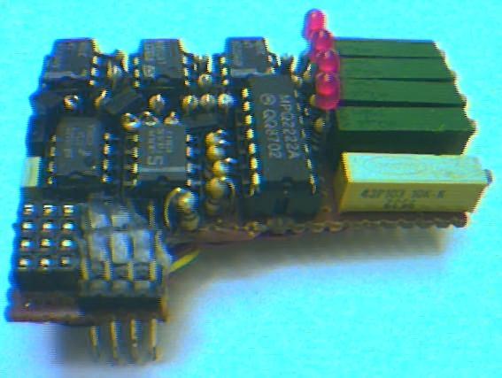
The above circuit board contains 4 obstacle detection circuits. One 555 timer was used to drive the 4 ultrasonic transmitters, and one LM358N were used per ultrasonic receiver. Due to limited space on the board, a transistor array containing four 2N2222 bipolar transistors were used. The 4X3 female header are used to attache the ultrasonic Tx/Rx pair and the 4X3 male header plugs directly into digital ports 12-15 on the Handy Board.
Edge sensor
The robot will be running on a black surface with a white edge. It has to stay on the surface and not wonder off the platform on its own. Thus, it must be able to detect the white edge of the platform. Infrared Tx/Rx pair is ideal for this applicated because the distance between the sensors and surface will be very small if the Tx/Rx pairs were mounted under the robot. An advantage of this location is that they will not be affected by ambient lighting conditions.

Contact sensor
The robot's obstacle detection circuit will only inform the robot that there is an obstacle, not the distance between the obstacle and the robot. Therefore contact sensors are needed for the robot to determine that it has made contact or dumped into an object. The simplest solution was to use microswitches.
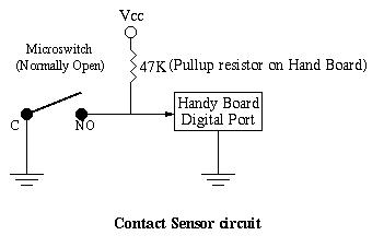
There are four microswitches (one on each side of the robot), connected to The Handy board's digital ports.
Batteries
The power sources chosen for this application are a 9V battery, regular and high capacity Ni-cad's. The motors are running off three 1.2V 4000mah Ni-cads for a total of 3.6V (Vmotor). The motor controller uses a 9V battery (Vmosfet) to properly bias the MOSFETs driving the motors. The Handy Board and its related electronics have its own 5V regulated voltage source (Vcc) provided by a 7.2V (6 600mah AA Ni-cad) battery pack. Vcc is electrically isolated to Vmosfet and Vmotor which shares a common ground.
Next section


Back to Dave's SUMO robot project page


Back to Dave's home page


Dave Chu
Concordia University
Electrical and Computer Engineering
1455 De Maisonneuve O. H851
Montreal, Quebec, Canada
H3G 1M8

Telephone: (514) 848-3115
Fax: (514) 848-2802
Email: dave@ece.de-spam.concordia.ca